of the energy fed to the primary is available on the secondary side, or,
Primary Energy = Secondary Energy (approximately).
Autotransformers
There is one other type of transformer in which we are interested-the autotransformer. In this de- vice, the primary and secondary windings are con- nected together metallically as well as magnetically, as shown in Figure 32. The primary and secondary windings are connected together and are both wound on the same iron core so that any lines of
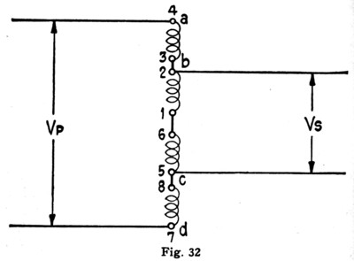
force that thread one winding also thread the other. From the previous explanations it can be seen that the voltages on the primary and secondary sides are directly proportional to the number of turns in the windings, just as in the regular transformer. Thus, in the transformer shown in Figure 32 if there
Page 42
are 150 turns between b and c, 750 turns between a and d, and 110 volts are connected across the primary ad, then the voltage across the secondary bc will be
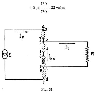
In Figure 33 is pictured an autotransformer with voltage E connected to its primary and a load R connected to its secondary. Now, in a transformer of regular type, the whole of the primary circuit current and of the secondary circuit current flow through their respective individual windings. But in the autotransformer the primary and secondary currents flow in opposite directions through the winding common to both circuits, so that the net current through the common winding (winding be
Page 43
in Figure 33) is only the difference between the foregoing currents. Thus, in the autotransformer in Figure 33, just as in a regular type transformer
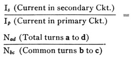
In the autotransformer, however,
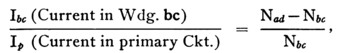
which accords with the statement above that
It follows, therefore, that resistance losses in an autotransformer are lower than in a transformer of the usual type having the same size wire in its corŁ responding windings. Conversely, less copper is re- quired in an autotransformer than in a regular transformer having the same load capacity and the same resistance losses, which is an economic adŁ vantage. The metallic connection between windings, on the other hand, is a disadvantage in power work, since it introduces the hazardous possibility of obtaining the full primary voltage on the load side of the device as, for example, if the primary circuit is operating under certain abnormal conditions.
Page 44
Transformers in Telephone Circuits
In the telephone plant we meet with numerous circuits containing transformers of one type or anŁ other. Repeating coils are transformers, some of unity ratio, some of inequality ratio, the type chosen for any particular circuit depending upon the use to which it is put. Induction coils, such as are associated with the ordinary subscriber's set, are transformers; in telephone repeater circuits we find still other designs of transformers and on many telephone circuits we find autotransformers used to improve transmission. It can be seen, thereŁ fore, that transformers are of extreme importance in telephone work, and in addition to theory some knowledge of the plant practices governing their use is essential.
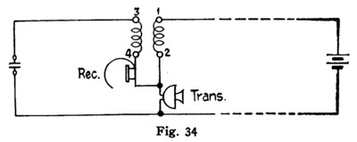
In Figure 34 is shown schematically the circuit of an ordinary subscriber's set containing an inducŁ tion coil. Here the fluctuations in current value in winding 1-2 induces an E.M.F. in winding 3-4 and this E.M.F. sets up a current which passes through the receiver.
In Figure 35 is shown an autotransformer as usuŁ ally connected on circuits to improve transmission characteristics. Here the inequality of the turn ratio is used to raise the apparent impedance of a
Page 45
section of line to make it equal to the impedance of the section on the other side of the transformer. The autotransformer is used because it permits the
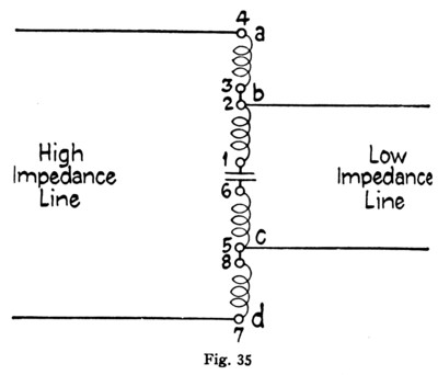
wires of the adjacent sections to be connected meŁ tallically, and therefore permits them to be used for direct current signalling.
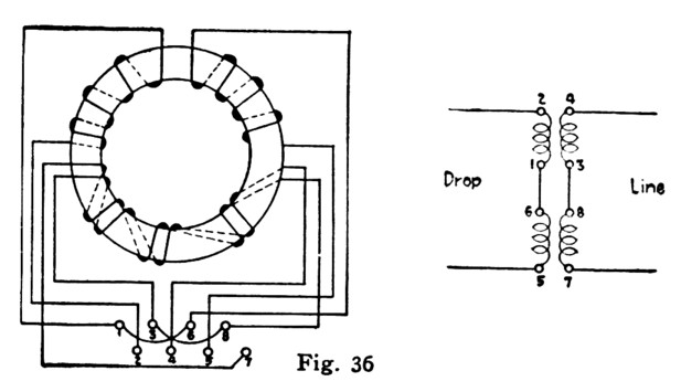
The repeating coil, which is one of the most comŁ mon pieces of telephone apparatus, has the followŁ ing construction and operating features. Each coil has four windings which are wound on a toroidal or doughnut-shaped iron core, and as usually emŁ ployed, two of the four '"unit" windings are conŁ nected in series to form a primary or "line" windŁ ing, and the remaining two in series form the secŁ ondary or "drop" winding. In telephone work it is essential that the two unit windings which make up the line winding have exactly similar electrical Constants, and to this end they are wound on the
Page 46
iron core side by side. Similarity between the unit windings used for the drop winding is not so imŁ portant, so these, for economic reasons, are wound on the core separately. Figure 36 shows the posiŁ tion of the unit windings on the core, and gives an idea of the different methods of placing the wire on the core.
On toll circuits, high-grade coils of special conŁ struction are used. In these coils, "stability" is an important consideration, that is, the construction must be such that the coil constants, particularly inductance, do not vary. It will be appreciated, from our discussion of magnetic substances, that if the iron core of a repeating coil becomes satuŁ rated, the change in the number of flux lines for a given change of current will become smaller. Also, that due to the residual effect, saturation of the core will influence its reaction to current flow. To prevent this saturation, such coils may have gaps cut in their cores, and these gaps filled with iron dust. By this construction the reluctance of the magnetic circuit is increased and the danger of saturation is minimized.
Page 47
In addition to acting as a ''phantom" or "simplex" coil, these transformers are frequently used to match lines of different impedances. In telephone circuits, it is highly desirable that all sections shall have the same impedance, and since it is frequently impracticable to build up a long circuit of sections having equal impedance, we frequently use coils to improve impedance conditions. For instance, if we wish to connect a line having a characteristic imŁ pedance of 1130 ohms to one having a characteristic impedance of 700 ohms we can improve transmisŁ sion on such a circuit by establishing the connecŁ tion through a transformer of such a turn ratio that, looked at through the coil, the 700 ohms looks like 1130 ohms. In other words, since the impedance varies directly as the square of the turn ratio, for this case we would choose a coil having a turn ratio determined as follows:
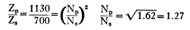
or as near that ratio as possible.