| Hacked / Modified BD-71 | ||||
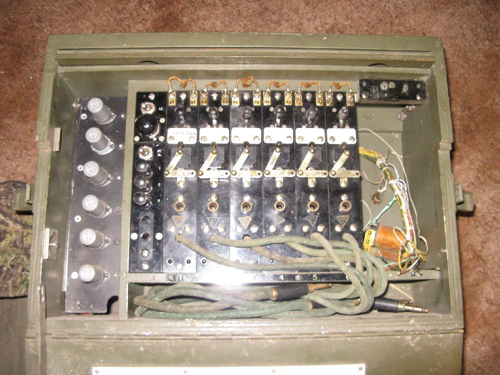
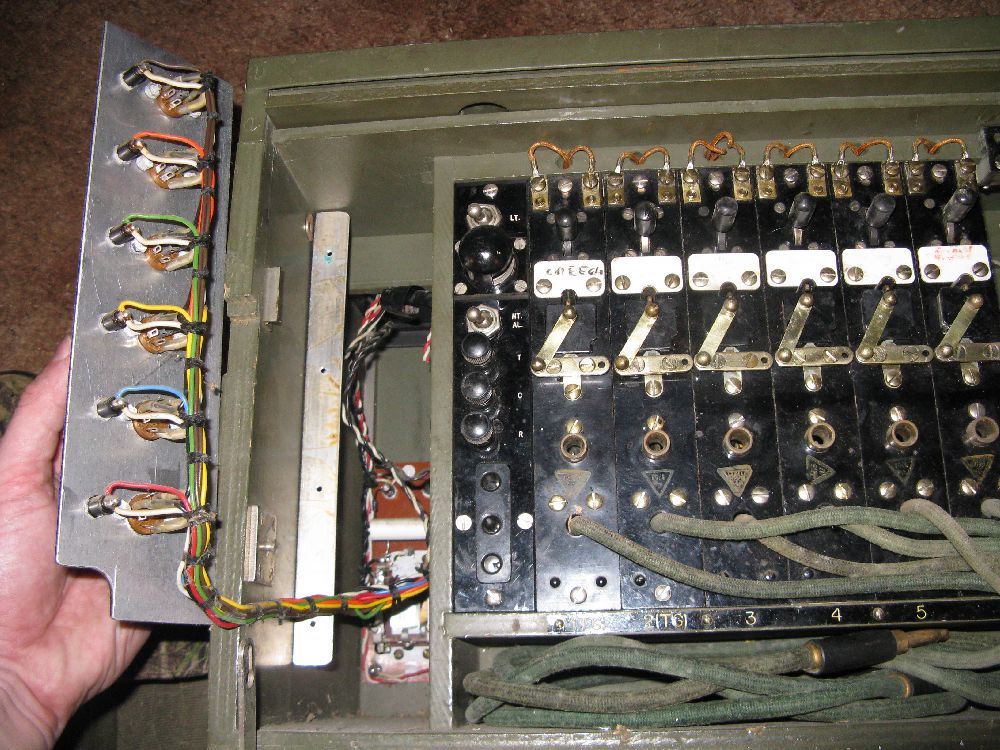
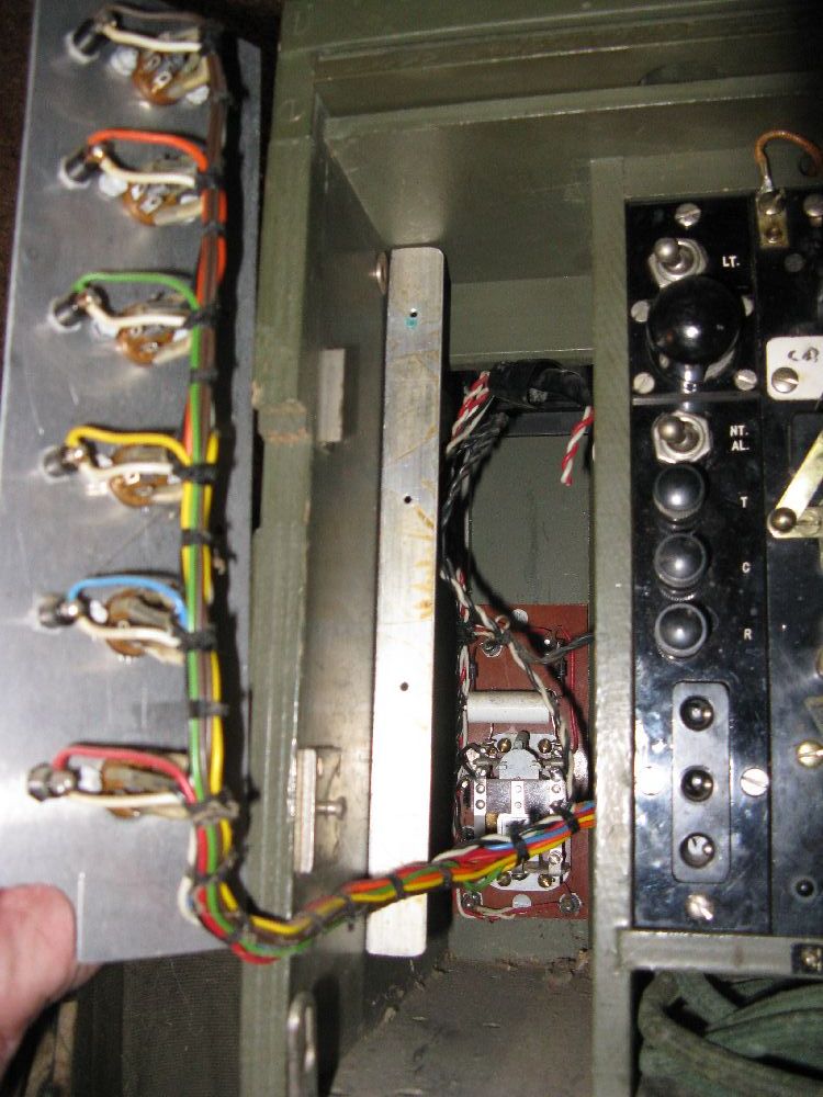
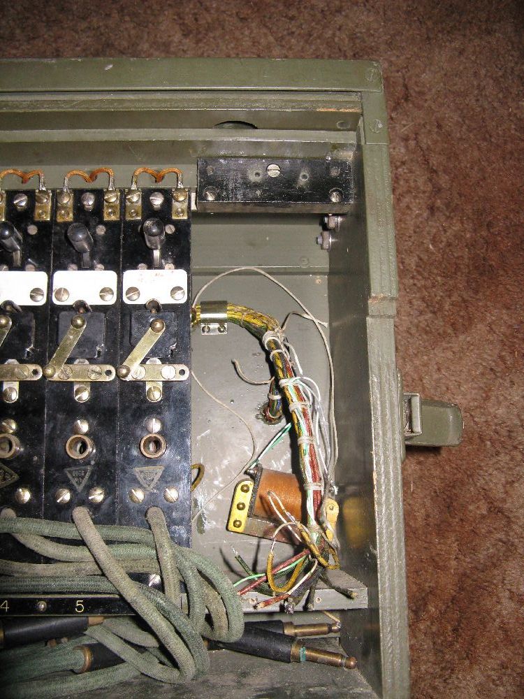
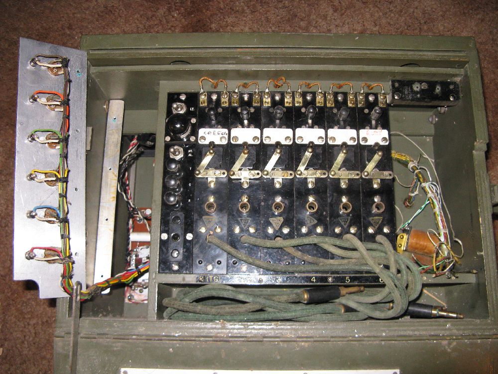
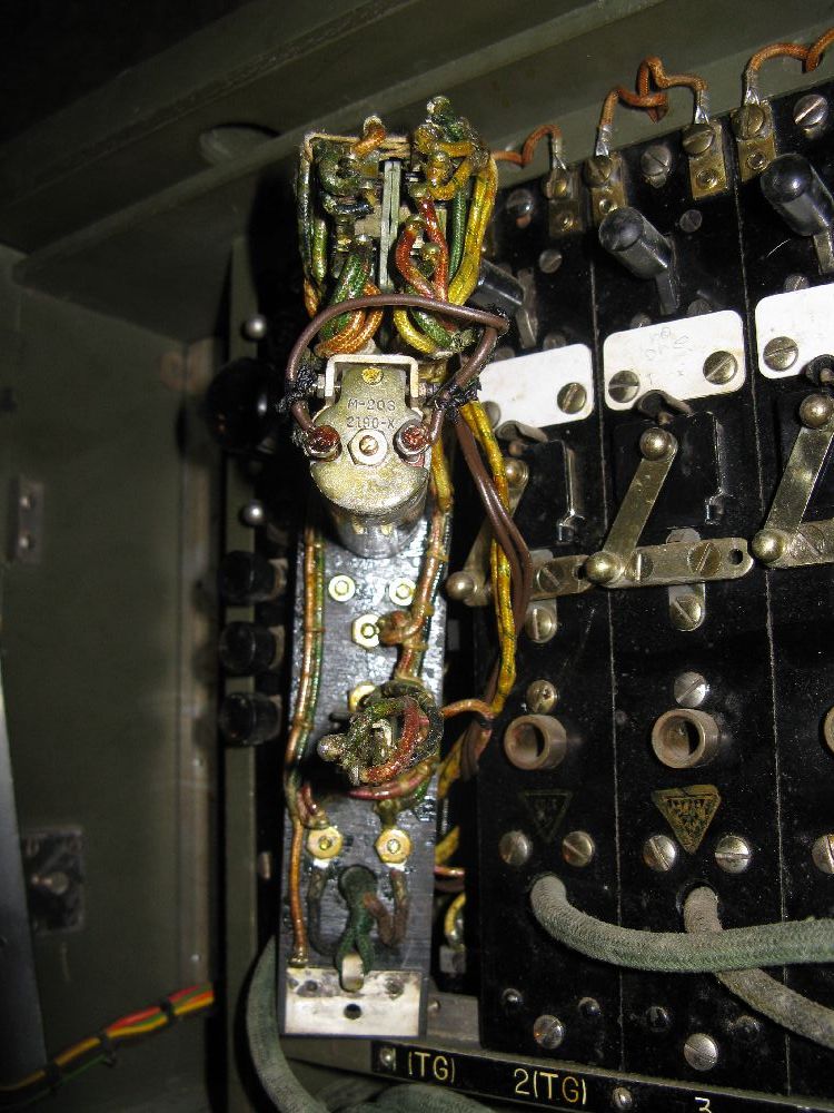
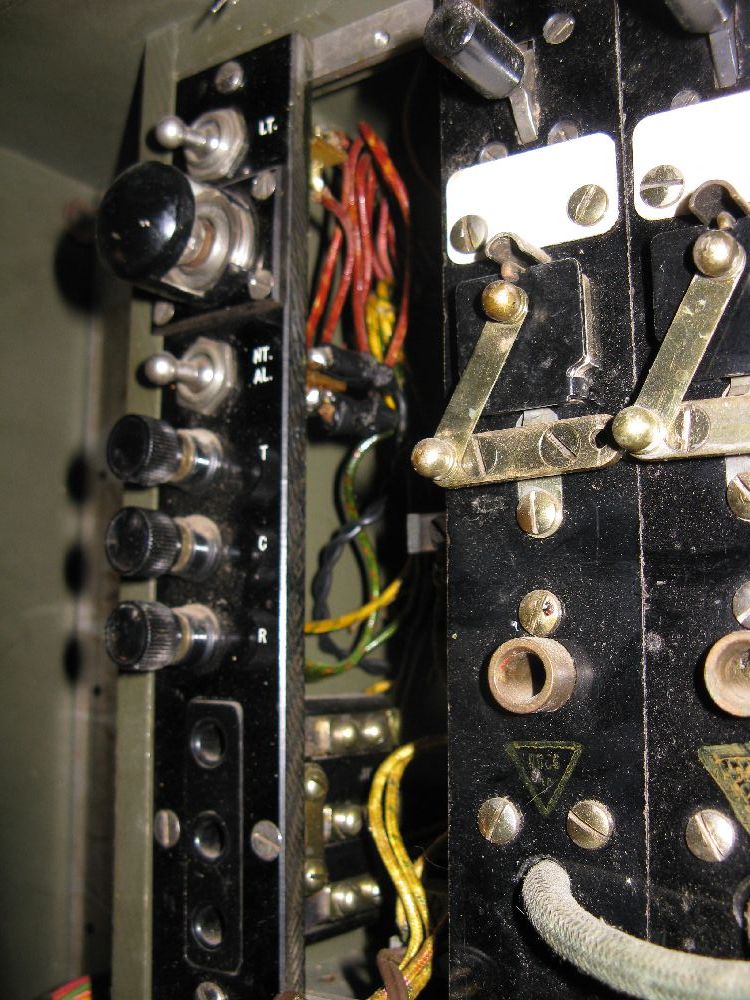
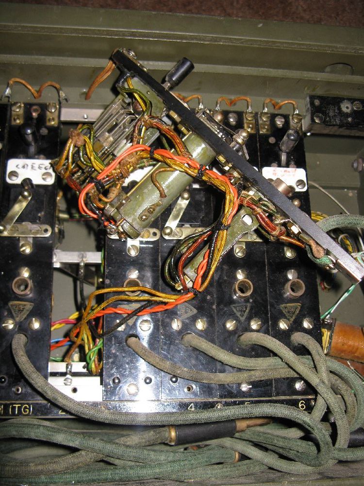
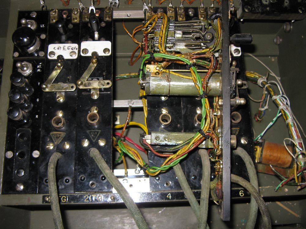
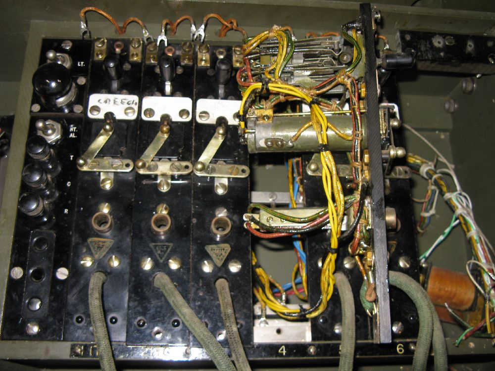
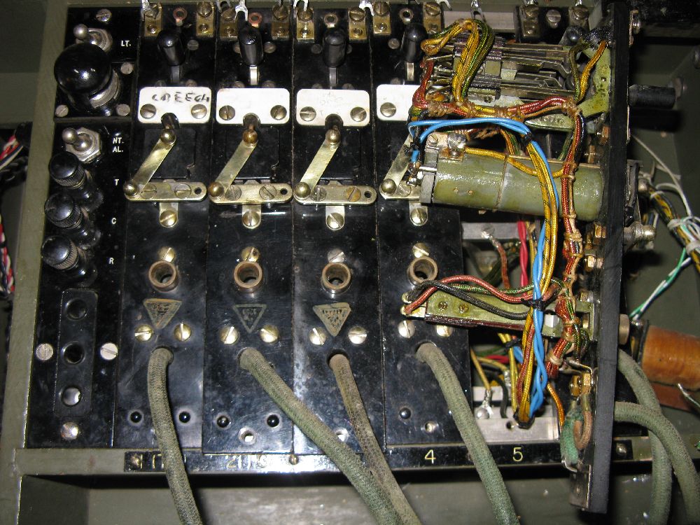
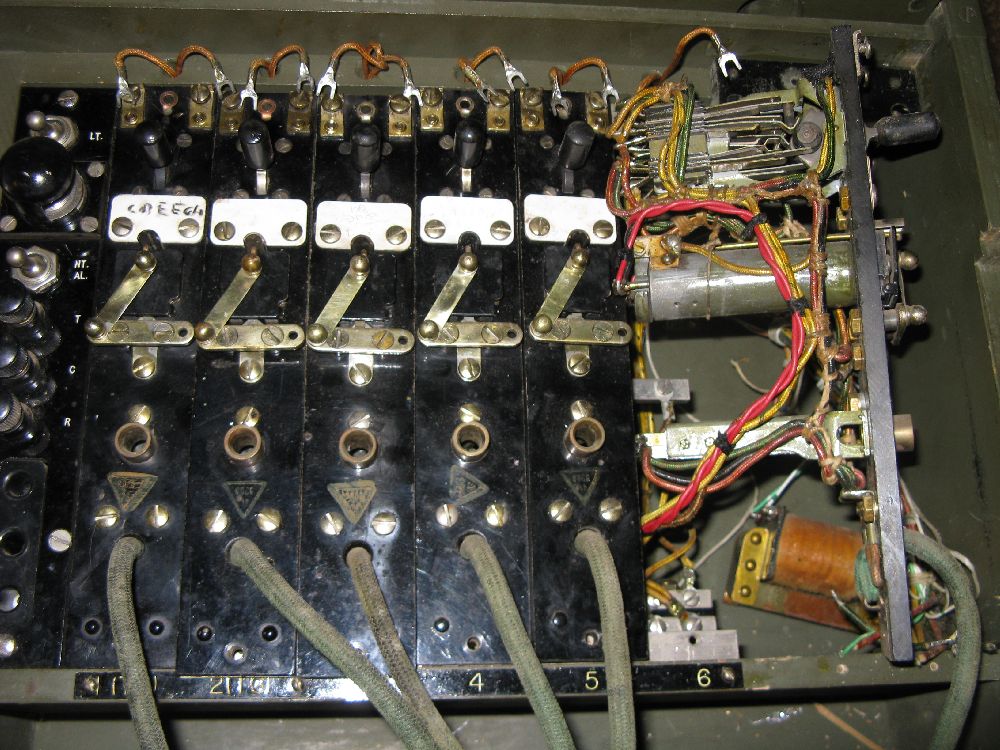
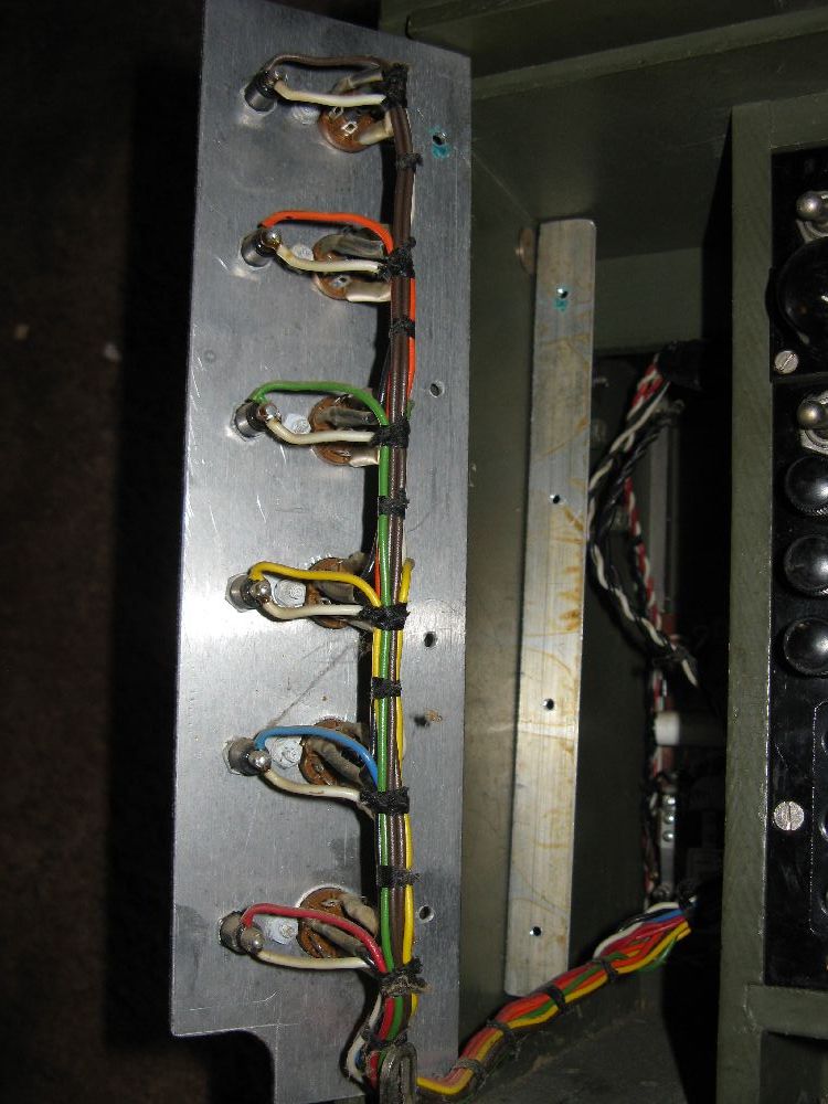
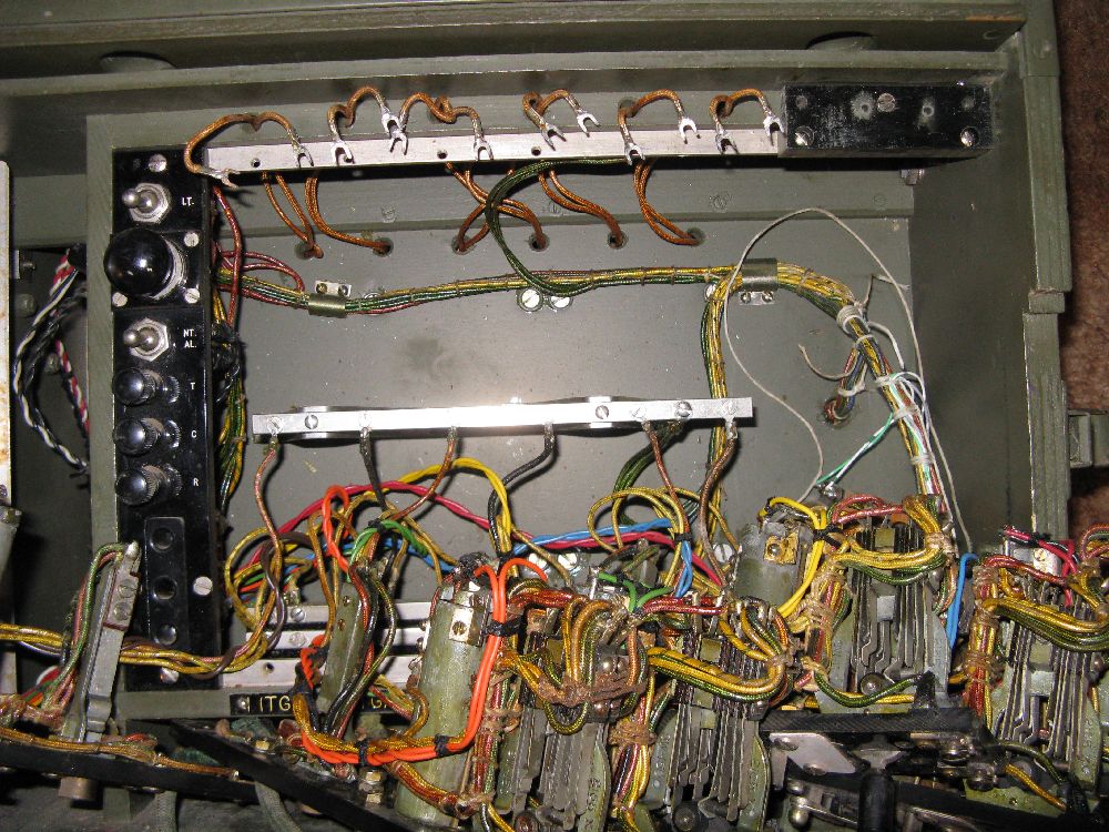
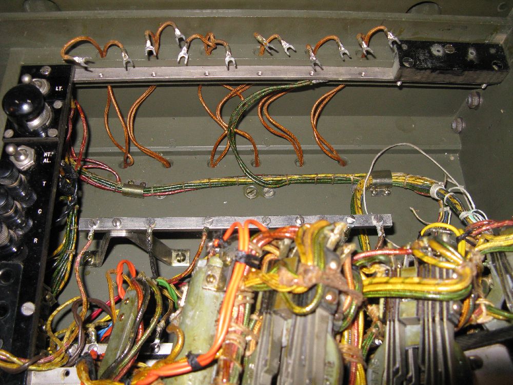
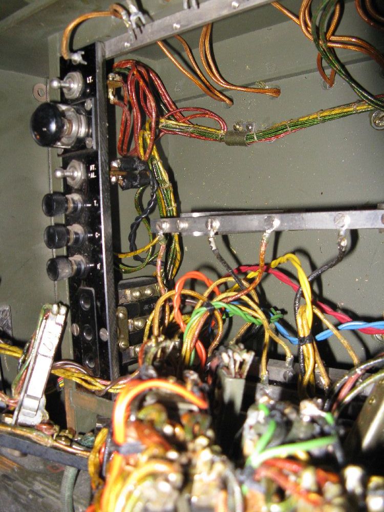
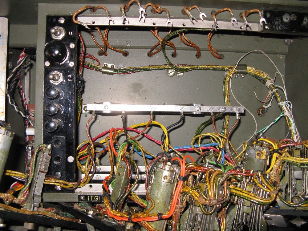
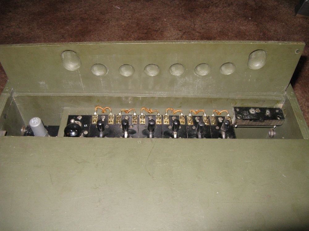
| This BD-71 was sold to a friend as "operable"... Further questioning of the seller by my friend revealed that they believed it had been modified for use at a local garage / gas station. The modification on the left side has two sections, the front panel with 6 relays visible to the user and a second single relay panel hidden behind. I have not fully reverse engineered the mod but the coils each front relay connect in parallel to the drop coil on a corresponding EE-2 unit. I haven't measured the black posts next to each relay to see if they are diodes or insulated solder posts. (appear to be solder posts) The contacts of the 6 front relays are all connected in parallel and go to the relay mounted in the back of the left compartment. The rear relay has a pair of black wires that go to NT AL switch in order to get power from the 3V supply. The 6 front relays are Potter and Brumfield PW5LS 5000 ohm miniature socket relays. The rear relay is a Leach Relay Co. Type 1037 relay. My guess is by ringing the switchboard the ringing voltage would also trip one of the additional front panel relays. The front panel relay would in turn connect that specific drop to the outside line and the rear relay would make the outside line "off hook". This part of the mod appears mid 1950's vintage based on materials and techniques used. A rural area in the 1950's most likely had a live operator in the telco central office. (Picture Sarah on the Andy Griffith show) After WWII and Korea this equipment was most likely next to free as surplus. Someone probably went out and got 6 EE-8's and this BD-71. Each EE-8 was installed in a different location in the garage, i.e. parts, repair garage area, front desk etc. With the above mentioned modification a phone could be picked up, cranked and get to the C.O. operator without needing someone at the BD-71 to connect them. How this whole thing actually worked and worked in reverse (incoming outside call) I am not sure. I'll do more circuit analysis and post what I find out. The hack done to the right side appears to be done by someone different at a later date. I'm not sure if they wanted the panel for something else or why they only left a hook-up wired voice coil. Wires going to Coil,generator,bell unit (Operator's telephone set panel) in BD-71/2 On an intact BD-72 there are 10 wires 4 tan, 6 green 1. A-Bus (GN-38 non-switched lead (Line-2)) (Blue) 2. B-Bus (C-105 pin 1) (Yellow) 3. C-Bus (C-105 pin 2) (Yellow-Black) 4. D-Bus (GN-38 switch common (Line-1)) (Green-Red) 5. +3V (only goes to lamp fixture) (Green) 6. Switched Light Lead from LT (Red-White) 7. Switched Bell Lead from LT (Red-White) 8. Handset Common (C-105 pin 3) (Green) 9. Handset Receive (common point between 2 capacitors) (Green-Red) 10. (Blue) to A-Bus or A Terminal 05-26-2010, confirmed all 10 wires on hacked BD-71 go to locations listed above and match color code. |
||||
 |
 |
 |
 |
 |
 |
 |
 |
 |
 |
 |
 |
 |
 |
 |
 |
 |
 |
||