a. Operator's Set.
(1) Generator Circuit.
Select any switchboard unit and see that the line terminals in the terminal compartment which correspond to this unit are clear. Raise the key of this unit, and while holding it in the RING position (up), turn the generator crank on the telephone panel (to the right of the switchboard units) rapidly for several turns. It should turn easily. Short-circuit the line terminals of the same unit, raise the key. and turn the generator again. It should turn hard, as if a drag had been placed upon it.
(2) Transmitting and Receiving Circuit.
Blow lightly and steadily into the transmitter while alternately depressing the key of any unit to the TALK position (down) and restoring it to normal. You should hear the sound (sidetone) strongly in the receiver while the key is depressed but not when it is restored to the normal position
b. Switchboard Units.
Connect a serviceable field telephone to the line terminals of the first switchboard unit. Operate the night-alarm (NT AL) toggle switch, located on the jack panel to the left of the switchboard units, by pushing the switch to the right. Turn the generator of the test telephone. The shutter of the unit should fall and close the circuit to the night-alarm bell, which should start ringing. Restore the shutter, which should stop the ringing. Raise the key of the unit and ring into the test telephone by turning the generator of the switchboard. This should operate the buzzer (or bell) of the test telephone. Depress the key of the unit to the TALK position and talk and listen from the switchboard to another man at the test telephone. Each voice should be heard dearly in the other receiver. Test eadi unit of the switchboard in a similar manner by connecting the test telephone to each pair of line terminals in turn and repeating the foregoing test.
c. Lights.
The lamp on each side of the switchboard units should light when the lamp toggle switch (LA) is pushed to the right. The reflectors may be adjusted by turning them so that they focus the light across the designation strips of the switchboard units. To conserve batteries, use the lights only when necessary.
7. LINE CONNECTIONS.
a. Terminals.
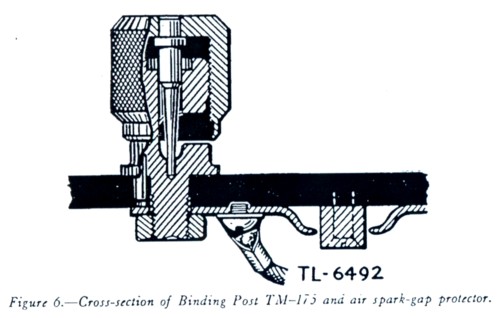
In the terminal compartment, each pair of binding posts for the line wires is numbered to correspond with the switchboard unit to which it is connected. These numbers run from right to left when the back of the board (see fig. 4) is faced. At the left of the line terminals are similar binding posts for the telegraph legs, marked TG 1, TG 2, TG 3, and TG 4, which are connected to the center tap on the line side of the repeating coil in the line circuit to which it is connected. The last binding post on the left marked GROUND is for the ground connection for the switchboard only. A metal bar connected to this terminal runs along the under side of the terminal strip underneath the two rows of binding posts, furnishing an air spark-gap to ground between the metal bar and the base of each binding post for protection against lightning. (See fig. 6.)
b. Terminating Local Circuits.
Connect the line wires of the trunk and local circuits entering the switchboard and the telegraph legs of sim-plexed circuits, if used, to the binding posts in the terminal (top) compartment. Tie them to a support in such a way that a drip loop is provided to prevent rain from running down the wire into the switchboard and so that there is no strain on the terminal connections. Attach tags showing the circuit designation to the wires close to the switchboard. The wires may enter the terminal compartment from either end. Remove about 3/4 inch of insulation from the wire, leaving 1 inch of insulation on the end to prevent the wire from untwisting. Place the bared part of the wire in the binding post slot and turn down the head tightly with the fingers. Caution: Do not use pliers.
c. Terminating Trunk Circuits.
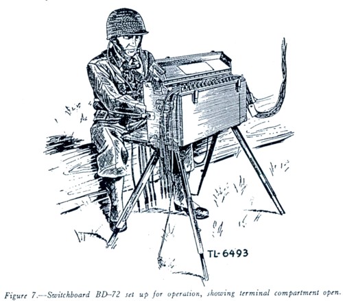
Since trunk circuits often are extended along the axis of communication, it may be desirable to have the wires of all trunk lines enter the terminal compartment at one end and extend through the switchboard, with about 3 feet being allowed to hang freely from the opposite end. (See fig. 7.) When the extended lines have been run and tested and are known to be free from trouble, they can be spliced onto the 3-foot extensions without disconnecting the circuits from the switchboard. After the forward switchboard takes over operations, the trunk lines are removed from the binding posts and the bared portions of the wires taped. Continuity of communication is maintained by doing this.
d. Grounds.
A ground wire should be run from the ground binding post to a suitable ground rod or other buried metallic body with a large area of contact with the earth. Since most of the installations of this switchboard will be in the field away from water pipes and similar good grounds, ground rods are necessary equipment. Because the lowest possible resistance to ground is essential for protection, care must be exercised in driving the rods to their full length and preserving a firm close contact between the rod and the soil. The tendency of the rod to whip when being driven will be reduced by using a small hammer or hand ax. In selecting-the location for the ground rod, select the dampest or most moist site available. The installation need not be immediately adjacent to the switchboard, provided the wire connection does not appreciably increase the resistance of the ground connection. Be sure that the rod to be used is free from all paint or grease and that the ground wire can be securely fastened to the rod.
e. Separation of Trunks and Locals.
In general, connect trunk circuits to the lower numbered line terminals on the switchboard. Connect trunk circuits over which it is desired to operate simplexed telegraph circuits to lines 1 and 2 on the 6-line switchboard or to lines 1, 2, 3, and 4 on the 12-line switchboard, since these are the lines in which repeating coils have been connected. Connect local circuits to the higher numbered terminals at the other end of the switchboard. This makes it easier to distinguish between trunk and local calls.
f. Wire Arrangement.
Arrange all wires so that they lie behind the metal corner posts on each end of the compartment. Close the cover while holding the sides open. The partially opened sides provide ample clearance so that the cover may be completely closed and latched with the wires in place.
g. Circuit Designation.
The designation of each circuit, that is, the code name of the central or installation or the number of the local telephone to which the unit is connected, should be entered in pencil on the designation strip just below the key of each unit. The drop shutters of units which are not to be used should be locked in the UP position by the spring locking bars.
8. TO INSTALL SWITCHBOARDS IN PARALLEL.
To obtain additional line capacity, an auxiliary BD-71 may be connected in parallel with either a BD-71 or BID-72, and the combination can be operated as a single switchboard, using the operator's telephone set of only one of the switchboards. Place batteries in switchboard to which the operator's set will be connected (par. 5b). Place the switchboards adjacent to each other. If one of the switchboards is a BD-72 (12-line), it will be necessary to place them approximately at right angles to each other in order for all cords to reach a jack. It is impracticable to operate two BD-72's connected in parallel. (See par. 9 for method of trunking between switchboards.) Connect the terminals marked +3V, A, B, C, and D of the multiple terminal strip in the rear compartment of one switchboard to the similarly marked terminals in the rear compartment of the other switchboard. These connections may be made with field wire or any suitable insulated wire. Place the wires over the sponge-rubber closure at the left edge of each case before closing the cover of the compartment. The outlet provides enough clearance for all necessary wires with the cover shut and latched. Do not plug in the second head and chest, set. If it is desired to use the night alarm and/or lights of the second switchboard, four BA-30's should be installed in the proper (left-hand) side of the battery case in the second switchboard. In an emergency, if extra batteries are not available, the night alarm and the lights of the second switchboard may be operated from the batteries of the first by installing an additional wire connecting the �LT terminal on each of the multiple terminal strips together. In any case, regardless of what battery is used for the night alarm and lights of the second switchboard, the night alarm and light switches on the switchboard must be turned on in order for them to operate.
9. TRUNKING BETWEEN SWITCHBOARDS.
When two switchboards connected in parallel are installed in a manner which prohibits the plugging in of any unit cord in all of the other unit jacks, best use may be made of the switchboards by trunking between them. This is accomplished by reserving, for trunking, one or more units on the left-hand switchboard and a like number of units, or corresponding positions, on the right-hand switchboard. Units selected should be from those not equipped with repeating coils, and each unit should be plainly marked on the designation strip as an interposition trunk. Each interposition trunk unit on the left-hand switchboard should then be connected at the terminal strips with field wire to the corresponding interposition trunk unit on the right-hand switchboard. Any connection to be made between the two switchboards where the unit cords will not reach may then be made through these two interposition trunk units which are connected.
10. OPERATION.
a. Operator's Equipment.
The operator should be seated in a comfortable position on an improvised seat in front of the switchboard so that he may observe all the switchboard drops and conveniently operate the keys and generator and handle the cords. The head and chest set should be adjusted and the toggle switch on the chest unit operated to close the transmitter circuit. This switch may be left in the operated position continuously, since no transmitting battery is used until the key of one of the units is operated.
b. Incoming Call.
(1) An incoming call is indicated by the falling of the signal drop of the calling line, which will cause the night alarm to operate if the night-alarm switch is on. Depress the key of that unit to the TALK position (down) and answer the party (or central) calling, at the same time picking up the calling party's plug. After determining the party (or central) to be called, restore the calling party's key. Ring the called party by raising the key of that unit to the RING position (up) and turning the generator rapidly several times while holding the key in the UP position.
Caution: Be sure to restore the calling party's key before ringing the called party. With the calling party's key and drop shutter both down, operation of the generator will result in ringing back the calling party, which is undesirable.
(2) Immediately after ringing, depress the called party's key to the TALK position and, if it is a local call, immediately insert the calling party's plug into the called party's jack. If it is a trunk call, pass the call to the distant operator before making the connection. After the connection has been made, the operator's telephone is bridged across the connection, enabling him to supervise the call. The called party's key may be left down until conversation has actually begun or, in the case of a trunk call, until the call has been passed to the distant operators. When the call has been supervised, the called party's key and the calling party's drop should be restored. In case it is necessary for the operator to answer another call before he has properly supervised the first connection, he restores the key but leaves the drop down and proceeds to handle the other call. He then goes back at the first opportunity and supervises the first connection, restoring the drop after he has done so. A drop should not be restored on a connection until it has been supervised, and when left in the DOWN position, it indicates a connection that still requires supervision. A connection that has been established and is being used is supervised by depressing the key of the called party's unit, listening, and challenging if necessary. Care should be taken that keys on two connections are never at the same time in the TALK position, as the two circuits will thus be coupled through the operator's set, resulting in crosstalk on both. After talking to either party, always restore his key before commencing any other operation.
c. Completed Call.
When the conversation is completed and either party rings off, that is, turns the generator of his telephone, the drop of the calling party's unit will fall. The operator should depress the key and answer the signal to see if either party desires another connection. NOTE.�This operation has been performed in figures 1 and 2. If no reply is received, take down the connection and restore the drop and key. The drop shutter of the other unit will not fall, since the drop of the unit was removed from the circuit when the plug of the calling party was inserted in the jack of that unit. In case another call is desired by either party, the operator must ascertain which party it is who desires another connection, by asking which party is calling.
d. Conference Calls.
When a calling party requests a simultaneous connection with two or more called parties, restore the calling party's key. He may hold the line or not, as he desires. Ring the first of the called parties, depress this party's key and when he answers, advise him to hold the line for a conference call. Restore his key and insert the calling party's plug in his jack. Pick up the first called party's plug and ring the second called party. Depress this party's key, and when he answers, advise him also to hold the line for a conference call. Restore his key and then insert the first called party's plug into the second called party's jack. Extend the connection in a similar manner to each of the called parties in turn. When the last of the called parties has been connected, restore his key, depress the key of the calling party, and, if he is not already on the line, ring him. When the calling party answers, inform him that all parties are now on the line. When the conversation has begun, restore the calling party's key and drop. All parties are now bridged together (at the switchboard) so that each can talk or listen to any of the others. The drop of the calling party remains bridged across the connection for a supervisory signal as in an ordinary call. The drops of all other parties have been removed from across the connection, since the plug of the preceding party is in each jack. The connection may be supervised by depressing the key of any one of the connected units.
e. Straight-Through Connection.
When two parties desire a straight-through connection so that either party can ring the other without operating the drops or requiring the services of the operator, the units may be cross- patched, that is, the plug of one unit inserted into the jack of the other and vice versa. This disconnects both signal drops from the circuit and provides a direct connection between the two lines. Since neither party is then able to signal the operator, the operator should be advised as to how long the through connection is desired.
f. Night-Alarm Circuit.
The night alarm consists of a bell which rings when any drop falls and stops when the drop is restored. The night alarm may be turned on or off by the toggle switch marked NT AL on the jack panel to the left of the switchboard units. This switch ison when it is pushed to the right and off when to the left. It is not ordinarily used when an operator is at the switchboard, but should be turned on at night and at other times when it is necessary for the operator to leave the switchboard. The night lights are controlled by a similar toggle switch located on the jack panel above the left-hand light. The lights should be used only when necessary in making connections at night.
11. SPECIAL INSTALLATION.
a. Emergency Installation Employing a Field Telephone as an Operator's Set.
If the transmitting and receiving or generator circuits of the operator's telephone set should fail and cannot be repaired immediately, a field telephone may be used as an operator's set. Test the telephone to insure that it is in proper operating condition. Plug the head and chest set into the jack at the top of Telephone EE-8, EE-8-A, or EE-8-B (or connect the transmitter, receiver, and common leads to the proper corresponding binding posts on other types of telephones), and connect the spare switchboard cord furnished with the switchboard to the line binding posts of the telephone. Place the telephone flat against the right side of the switchboard with the generator handle to the front, and pass the switchboard carrying strap around it and through the loop on the leg casting. Double the strap back to the buckle and tighten it so that the telephone rests securely against the side of the switchboard and is flush with the front face, so that the generator handle can be easily rotated by the operator. The spare switchboard cord is used to connect the telephone to the jacks of the calling and called parties in turn. If no spare cord is available, field wire may be used to connect the telephone line terminals to the line terminals of one of the switchboard units at the terminal strip in the top compartment. The cord of this switchboard unit may then be used as an operator's cord.
b. Operation When Using a Field Telephone as an Operator's Set.
When a field telephone is used in this way, the keys on the switchboard units are not used and should be left in the normal position. To answer a call, insert the operator's plug into the jack of the calling party. Determine the party to be called and then withdraw the plug and insert it into the jack of the called party. Ring the called party with the generator of the telephone and, on a local call, immediately insert the called party's plug into the calling party's jack, completing the connection. In the case of a trunk connection, do not complete the connection until