REPAIR INSTRUCTIONS
Note. Failure or unsatisfactory performance of equipment used by Army Ground Forces and Army Service Forces will be reported on wD. AGO Form 468 Unş satisfactory Equipment Report) ; by Army Air Forces, on Army Air Forces Form 54 (Unsatisfactory report). If neither form is available, prepare the data according to the sample form reproduced in rigure 34.
Section I. THEORY OF TELEPHONE EE-8-(*)
43. Circuit Elements
a. Handset TS-9-(*).
Handset TS-9-(*) contains a high output nonpositional transmitter and a high fidelity receiver. The transmitter element is of the granular carbon type. The diaphragm, carbon inclosure, and frame are constructed in unit form making the element readily replaceable. The receiver element is a permanent-magnet, diaphragm type. It gives high fidelity response over the audible frequency range, and is effectively compensated for stable performance over a wide temperaş ture range.
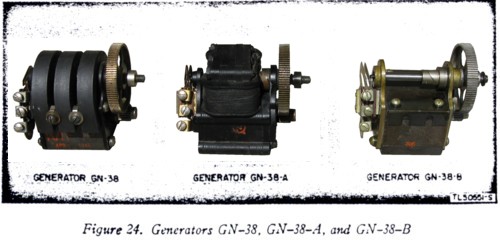
b. Generator (fig. 24).
Generator GN-38 has three small cobalt steel permanent magnets arranged in two pole faces about an armature. Generator GN-38-A has a rotating magnet with stationary coils. Genş erator GN-38-B has two stationary magnets and two pole pieces arş ranged alternately about an armature. The generator switch consists of spring contacts which in normal position connect the ringer across the line, but which upon rotation Of the crank disconnect the ringer and place the output of the generator across the line. The crank handle folds into the metal-faced recess on the right side of the case.
39
c. Ringer.
Ringer MC-131 is of the single-gong type. The ringer coils, armature, and clapper are mounted internally to the gong (figs. 6. 7. 8. and 20). When energized by ringing current, the armature operates the clapper about a pivot to strike alternately two internal projections of the gong rim. The acoustical output is high for a relatively low electrical input.
d. Holding coil.
The holding coil (Coil C-158) is bridged across the line circuit when the screw switch is in the CB position and the lever switch is released. With the lever switch depressed, the coil is disconnected. If the screw switch is in the LB position, the coil is permanently disconnected, independent of the lever switch position. The purpose of this coil is to provide a low resistance d-c path through the telephone for operating the line relay and holding the supervisory relay energized on a common battery switchboard. The holding coil has high impedance to voice-frequency currents to minimize transmission losses.
e. induction coil.
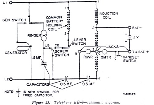
The induction coil (Coil C-105) is an autotrans- former with one continuous winding tapped at terminals 2 and 3 so as to form the 1-2 section, the 2-3 section, and the 3-4 section. ( See figs. 25 and 26.)
f. Lever switch.
The lever switch has two contacts which are operated by a hinged lever and plunger. The switch is held depressed by the weight of the handset which is hung on it. and is automatically raised by a spring when the handset is removed. The contacts are open when the lever switch is depressed and closed when the switch is released. The lever switch is used only on common battery circuits.
g. Capacitors.
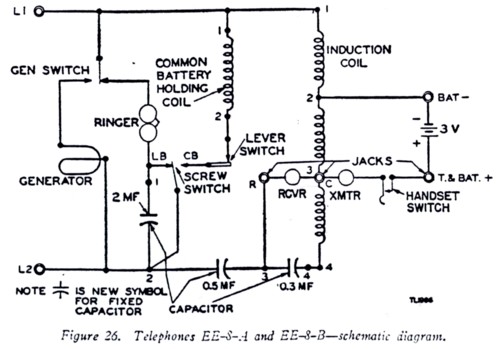
In Telephone EE-8, three physically separate capaciş tors, of 1.9-mf, 0.5-mf. and 0.3-mf capacitance are used. ( See figs. 25 and 27.) In Telephones EE-8-A and EE-8-B. Capacitor CA-355 comş prises a 2.0-mf. a 0.5-mf, and a 0.3-mf capacitance element, all assembled into one container and internally connected to the terminals numbered 1. 2. 3, and 4. (.See figs. 26, 28, and 29.)
44. Theory of Operation
The schematic diagram of Telephone EE-8 is shown in figure 25 and the schematic diagram of Telephones EE-8-A and EE-8-B is shown in figure 26.
a. Transmitting circuit.
(1)
The transmitter, receiver, induction coil, and the 0.3-mf capacitor are connected in an antisidetone circuit in which the impedance of these elements and the characteristic imş pedance of the average line (Wire W-110-B) are so balanced as to reduce the sidetone in the receiver to the proper level. This results in an effective gain since the effect of noise in the vicinity of the transmitter of the receiving telephone is reduced. The user also unconsciously speaks more loudly into the transmitter when he does not hear his own voice
40
loudly in the receiver. This results in effective transmitting gain. On lines shorter than the average, the sidetoue is more pronounced and the antisidetone effect is lessened.
(2)
41
the entire 1-4 winding of the induction coil and across terminals L1 and L2 to which the line is connected.
(3)
The antisidetone operation of the circuit results from the elecş trical balance between the impedance of the 3-4 section of the induction coil in series with the 0.3-mf capacitor, and the impedance of the line circuit consisting of 4 miles or more of Wire W-110-B connected to terminals L1 and L2. On shorter lines the antisidetone is less proş nounced, although still effective.
b. receiving circuit.
(1)
The induction coil, 0.3-mf capacitor, and receiver are so designed that the greater portion of the incoming line current will flow through the receiver over the voice-frequency range. This results in a maximum sound output.
(2)
The 0.5-mf capacitor is placed in series with the receiver to prevent the flow of direct current through the receiver, either from the batteries in the telephone or from the central office battery, when the telephone is connected to a common battery system. This capacitor also limits 16-cycle ringing current through the receiving circuit and permits the permanent connection of the listening circuit across the line.
(3)
The transmission loss through the ringer, or the ringer and the capacitor in series, and the holding coil is negligible because of the high impedance to voice-frequency currents of these elements.
c. signaling circuit.
The 1.9-mf capacitor in Telephone EE-8, or the 2.0-mf capacitor in Telephones EE-8-A and EE-8-B, is in series with the ringer when the screw switch is in the CB position. This capacitor prevents direct current from biasing the ringer and also preş vents the ringer from interfering with d-c signaling or supervision when the telephone is connected to a common battery system. The capacitor is short-circuited when the screw switch is turned to the LB position.